Vector graphics workflow
Software development is constantly growing. The film and multimedia industry are coming together as partners to provide a one stop shop by allowing applications to communicate via different file formats. One of the formats that have proven to be useful in both industries is the SVG (Scalable Vector Graphics) format. Its architecture algorithm is based on mathematical expressions. In simpler terms, in doesn’t suffer image noise & artifacts like bitmap formats such as PNG, TIFF, JPG and etc.
Inkscape’s SVG format uses multiple layers and paths, but most graphics applications can only parse this as a flat bitmap. There will times when an artist may want to animate and/or modify those layers in a compositing program but can’t due to limitation in the SVG importer. Natron however supports all layers and paths in the SVG file, this enables enhanced control over the vector graphics.
This tutorial will show you how to use vector graphics from Inkscape in Natron.
Inkscape
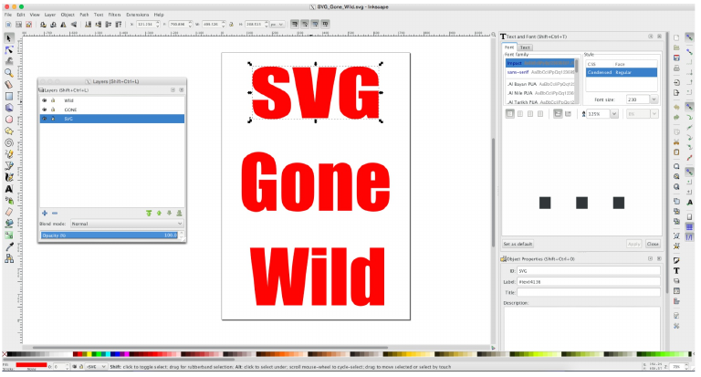
Inkscape has multiple ways to create vector graphics to be saved and imported into Natron. The default is to first create your document layout. This entails formatting the resolution for the project upon which your vector graphics will be displayed. Inkscape starts with one layer and you can draw and type your graphics on that layer or additional layers. You can then save the project to SVG file.
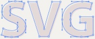
This image is SVG letters being converted to a group and layers for each word so that they may have their own layer/alpha channel in Natron.
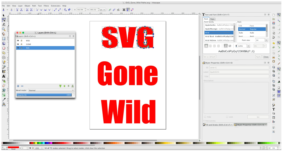
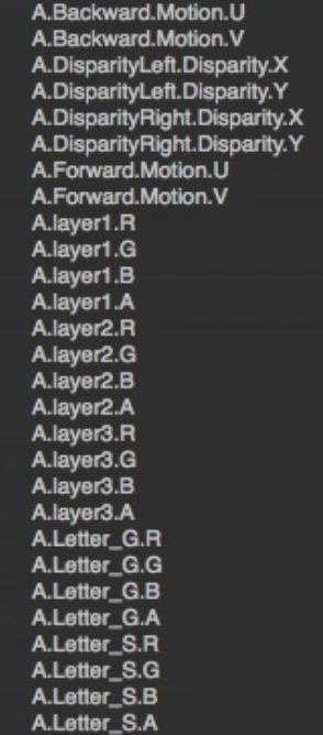
The image below is the same vector letters being converted to paths and eventually ungrouping each of the vector letters so that they may have their own layer and alpha channel in Natron.
Note
Remember to make sure that you convert your objects to paths, it is highly advisable to name each path with its separate id name. It will make it much easier to find Color.RGB and alpha channel names in Natron after loading the SVG file in the node graph.
It is also possible and good practice to select objects/paths and create groups of them. This will allow easy animation work-flows without having to duplicate animated key-frames if needed. Those groups will also show up as Color.RGB and Alpha channels in Natron.
Natron
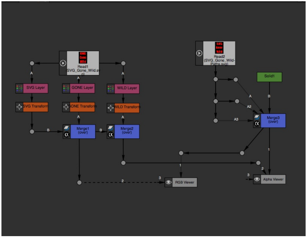
The image below is Natron with the SVG file loaded. We have two viewers displaying the Color.RGB and alpha channels generated from the SVG file.
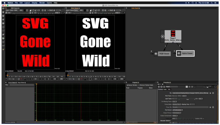
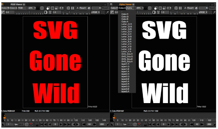
After you have loaded the file, you can check the Color.RGB/Alpha Channels headers to see how the layers, paths and groups are read. The ReadSVG node is multi-plane aware. The next few images are Natron screen captures of the headers, merge and shuffle nodes.
Note
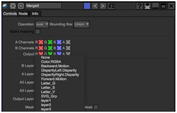
To clarify the Merge: Paths Channels image. In the SVG image, I broke apart the vector characters and converted them to paths. Then each letter of the SVG was giving the name assigned to that letter. That information got saved as individual Color.RGB/Alpha channels.
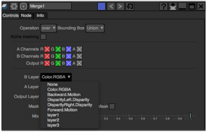
Be sure to look carefully at the Color.RGB and alpha headers in the images below. When your finished designing your vector document with layers/paths/groups, this is where the channels are displayed.
The Shuffle and Merge nodes are used to access multi-plane layers. Though they both can process the different SVG files objects, paths, layers, they work differently. As you can see in the image on the left the shuffle node display every channel(s) from a file and also copy channels from other files into the “A” input from the “B” input.
The merge node only perform mathematical blending operations on the inputs “B” and “A:A1000”. In order to access the alpha channels from the SVG file you must use the maskChannel mask inputs.
So plan your work before you start a project. Organization is key. Make sure that Layer(s), Object(s), Path(s) and Group(s) have logical naming conventions.
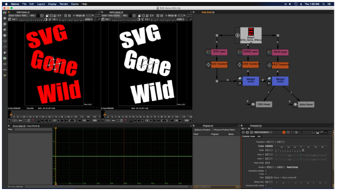
The node graph below shows how to extract individual layers using the shuffle node and the merge node. Both can extract the RGB layers and individual paths from an SVG file, but the Shuffle node allow you to pipe any of the layers or single channels to another node mask input.